Automotion Components Linear Ball Bushings
What is...
Product Selection
L1706
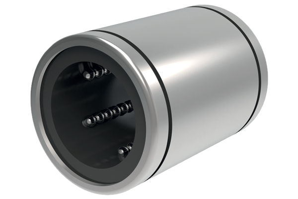
Closed, open + adjustable
L1712
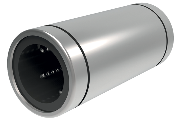
Double compliment versions
L1715
Compact versions
L1718
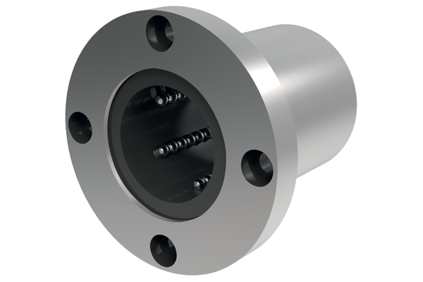
Front flanged standard
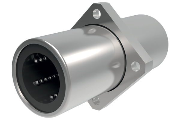
L1723
Front flanged double compliment
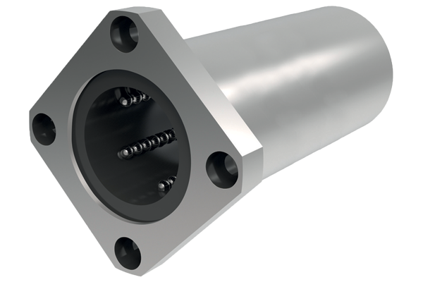
L1731
Centre flanged double compliment
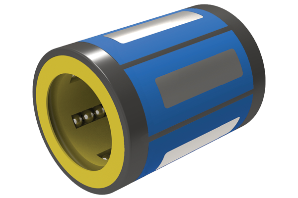
L1740
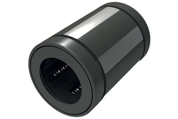
Superball bushings
L1750
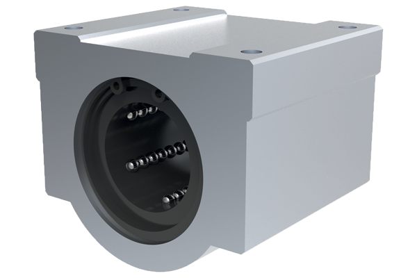
closed linear carriage
L1753
Open linear carriage
General Guidance
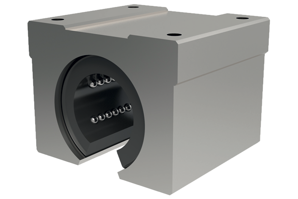
Linear Ball Bushings
Applications
- Computers and peripheral equipment.
- Recording equipment.
- Linear motion systems.
- Multi-axis drilling machine.
- Printing machines.
- Food packaging machines.
- Punching presses.
- Tool grinders.
- Assembly systems.
- Card selectors.
Interchangeability
Our Linear Bushing Systems are designed to have full interchangeability, with other manufacturers’ parts. For shafting see part numbers L1770 to L1785.
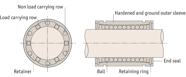
High precision retainer
The Single-body Retainer guides 4-6 ball circuits. It precisely guides the balls with a smooth motion.
Tolerance of Housing Bore
Normal fit is standard, pressed fit is for without clearance.
| Part no. | Normal fit | Pressed fit |
| L1706 to L1733 | H7 | K6, J6 |
| L1706...-1 to L1733...-1 | H7 | J7 |
Rigid outer sleeve
The hardened and precisely ground outer sleeve is made of bearing steel.
L1750 bushing carriages
Consists of light aluminium case and L1706 type Linear Bushing, so the installation can be finished simply by bolting. Longer life can be obtained by adjusting the orientation of the ball circuits in the linear carriage element against the direction of load.
Tolerance of shaft
| Part no. | Normal fit | Tight fit |
| L1706 to L1733 | h6 | k6 |
| L1706...-1 to L1733...-1 | f6, g6 | h6 |
Basic dynamic load rating C
The basic dynamic load rating is defined as the constant load both in direction and magnitude under which a group of identical Linear Bushings are individually operated. 90% of the units can travel 50Km without failing due to rolling contact fatigue.
Basic static load rating C0
If a Linear Bushing is subject to an excessive load or impact, a permanent deformation occurs between the raceway and the rolling element. The basic static load rating is defined as the static load that gives a prescribed constant contact stress at the centre of the contact area between the rolling element and raceway receiving the maximum load.
Superball linear ball bushings
- 3 x the load rating and 27 x the travel life of conventional linear bushings
- Self-aligning feature
Features
Higher load ratings
The uniquely designed Ball Plate (in the outside diameter of the bushing), is made of hardened steel. The precision ground groove is slightly larger than the ball size, which provides greater contact area between the balls and the ball plate, and as a result, provides 3 x higher load ratings of conventional Linear Bushings.

Self-alignment
The Ball Plate has a convex shape to provide a pivot point at the centre which allows self-alignment up to ±0.5°. This self-alignment capability eliminates any possibility of edge pressure caused by inaccurate machining, errors on mounting, or shaft deflection.
Tolerance of Shaft and Housing Bore
| Part no. | Shaft Ø d1 | Tol. h6 μ | Housing bore Ø d2 | Tol. H7 μ |
| L1740.010 | 10 | +0 to - 9 | 19 | +21 to -0 |
| L1740.012 | 12 | +0 to - 11 | 22 | +21 to -0 |
| L1740.016 | 16 | +0 to - 11 | 26 | +21 to -0 |
| L1740.020 | 20 | +0 to - 13 | 32 | +25 to -0 |
| L1740.025 | 25 | +0 to - 13 | 40 | +25 to -0 |
| L1740.030 | 30 | +0 to - 13 | 47 | +25 to -0 |
| L1740.040 | 40 | +0 to - 16 | 62 | +30 to -0 |
| L1740.050 | 50 | +0 to - 16 | 75 | +30 to -0 |
Technical Specs
Relationships between load ratings and the position of ball circuits
Load ratings of linear bushing are affected by the position of the ball circuits as shown below.
| No of ball rows | Maximum load rating | Minimum load rating |
| 4 | 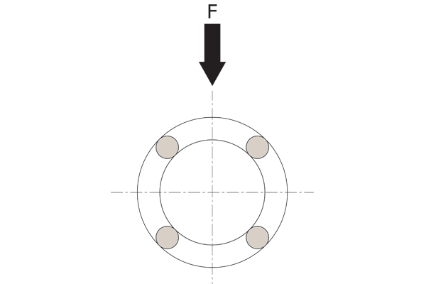 F = 1.41 x C | 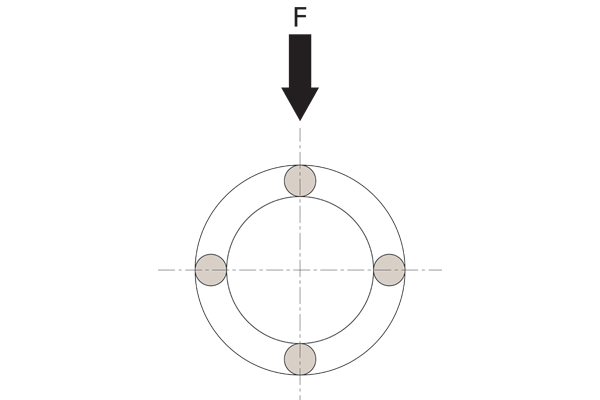 F = C |
| 5 | 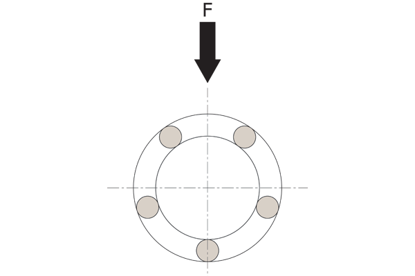 F = 1.46 x C | 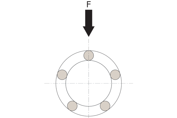 F = C |
| 6 | 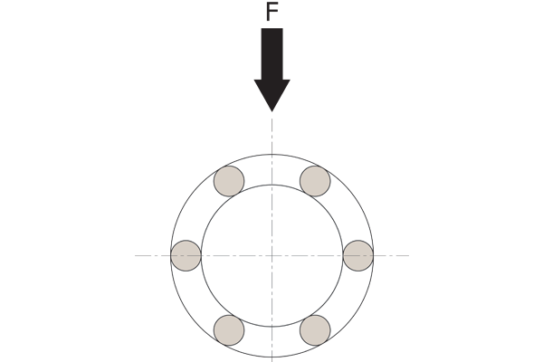 F = 1.26 x C | 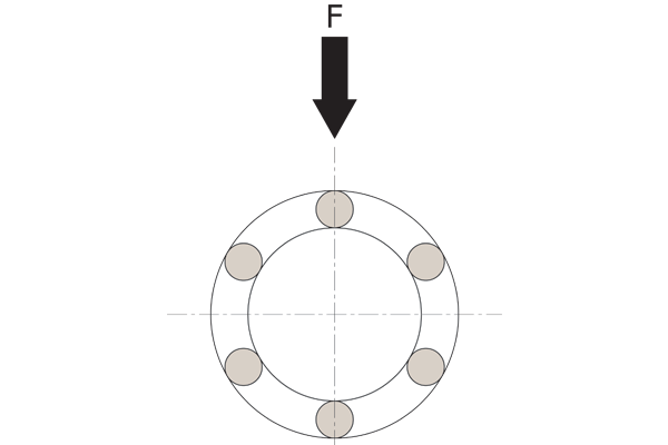 F = C |
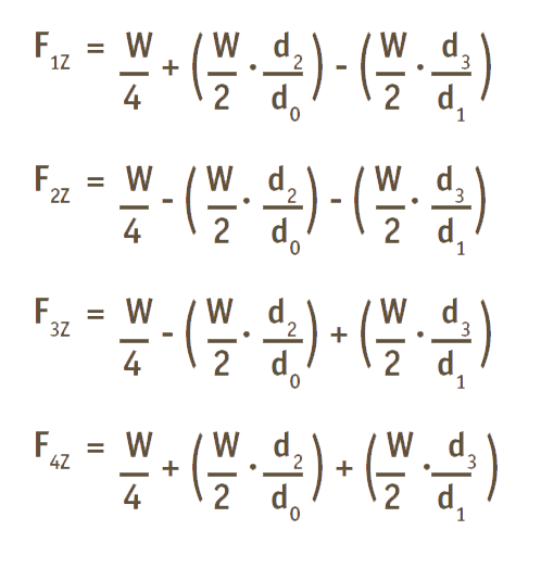
When designing a linear motion system it is necessary to consider how the application will affect performance. The following examples demonstrate how the position of the load andthe centre of gravity can influence product selection. When evaluating your application, review each of the forces acting on your system and determine the product that best suits your needs.
Horizontal application
For uniform speed or when stopped.
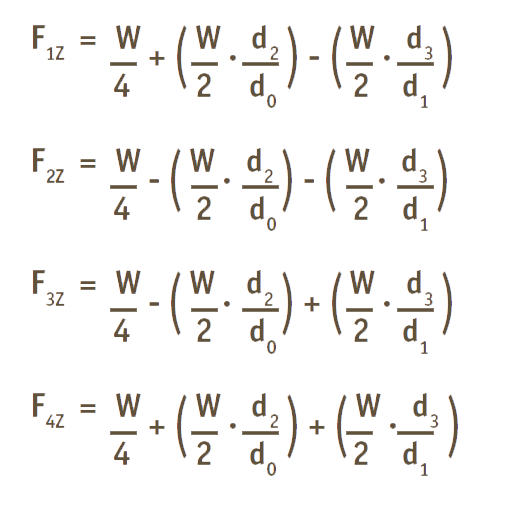
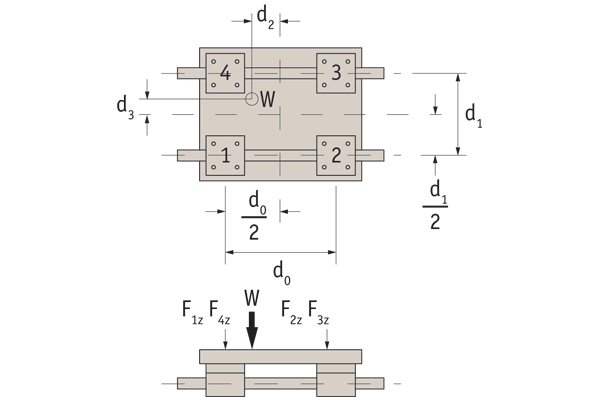
Horizontal application
For uniform speed or when stopped.
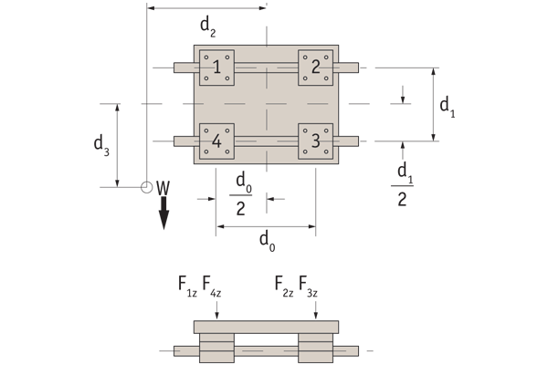
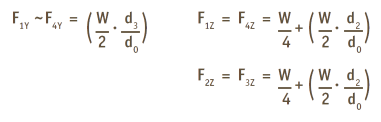
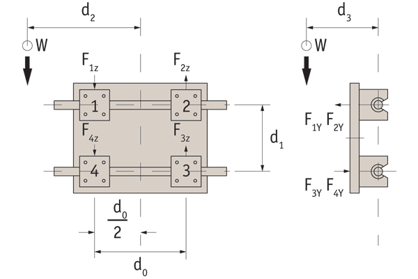
Side mounted application
For uniform speed or when stopped.
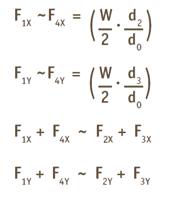
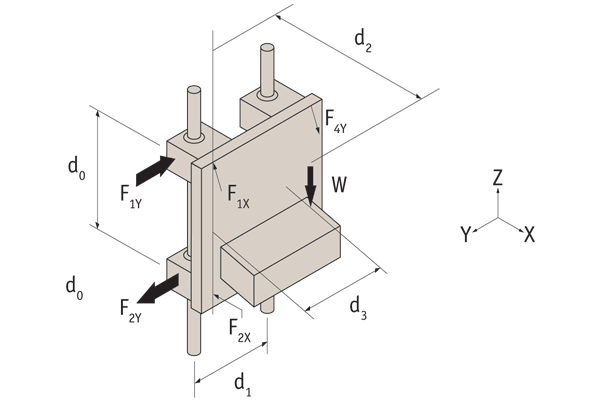
Vertical application
For uniform speed or when stopped. On start up/stop the load varies due to inertia in the system.
Friction
The coefficient of friction (μ) of Automotion Components ball bushings without seals is very low at approximately 0.001 to 0.003. When seals are used to retain lubricant or to prevent entry of foreign particles, friction resistance must be taken into account for determining total frictional drag. This protection measure adds to the frictional drag of the bearing system. There is a fine line between minimizing frictional drag and maximizing containment protection which is controlled by the addition or removal of seals, wipers or scrapers.
Linear bushings are used with grease or oil lubrication but in some cases can be used without any lubrication.
Grease lubrication
Before applying the grease, the anti-corrosive oil must be removed with kerosene or an organic solvent. The grease must be applied when the bushing is dry. Grease must be applied directly on the balls for linear bushing with seals. Lithium soap of viscosity mark (JIS No.2) is recommended for use.
Oil lubrication
There is no need to to remove the anti-corrosive oil when oil is used for lubrication. ISO viscosity grade VG15~100 oil is usually used according to the temperature ranges below. Drop the oil onto the shaft for lubrication, or supply it through an oil hole provided on the housing (see illustration below). However, dropping lubrication cannot be used on linear bushings with seals as the seals remove the oil.
| Operating temperature | Viscosity |
| -30°C to +50°C | VG 15 to 46 |
| +50°C to +80°C | VG 46 to 100 |
Static safety factor fs
A linear motion system may receive an unpredictable external force due to vibration or impact while it is at rest or in motion, or inertia as a result of starting and stopping. It is, therefore, necessary to consider the static safety factor against operating loads. The static safety factor (fs) indicates the ratio of a linear motion system load carrying capacity (basic static load rating, Co) to the load exerted thereon.
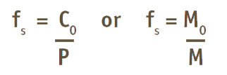
fs = Static safety factor
C0 = Basic static load rating (N)
M0 = Static permissible moment (Nmm)
P = Calculated load (N)
M = Calculated moment (Nmm)
To calculate a load exerted on the linear motion system, the mean load for calculating the service life and the maximum load for calculating the static safety factor must be obtained in advance. A system can receive unexpected excessive load when it is subject to frequent starts and stops, placed under machining loads, or when a severe moment is applied by overhanging loads. When selecting the correct type of a linear motion system for your application, be sure that the type you are considering can bear the maximum possible load when stopped and in operation. Both tables below specify the standard values for the static safety factors.
| Machine used | Loading conditions | fs Lower limit |
| Ordinary industrial machine | No vibration or impactVibration and/or impact | 1,0 ~ 1,32,0 ~ 3,0 |
| Machine tool | No vibration or impactVibration and/or impact | 1,0 ~ 1,52,5 ~ 7,0 |
For large radial loads
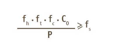
C0 = Basic static load rating (N)
fh = Hardness factor
fc = Contact factor
P = Calculated load (N)
ft = Temperature factor
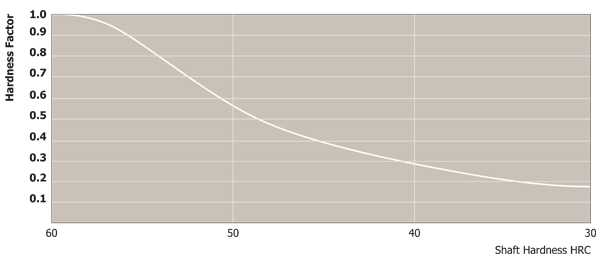
Hardness factor fh
To achieve the optimum load rating of the linear ball bushings, the shaft hardness must be 58 to 64 HRC. At a hardness below this range, the basic dynamic and static load ratings decrease. The ratings must therefore be multiplied by the respective hardness factors (fh).
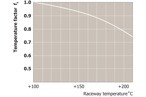
Temperature factor ft
For linear bushings used at ambient temperatures of over 100˚C, a temperature factor must be taken into consideration. For higher than 80˚C applications, the seals, end plates, and retainer must be changed for high temperature specifications. (Temperature range: -20˚C - +80˚C). Please note that the selected linear bushing in this case must be a model with high temperature specifications.
Contact factor fc
When multiple linear bushings are used moments and mounting surface precision will affect operation, making it difficult to achieve uniform load distribution. In this case, multiply the basic load rating (C or C0) by a contact factor selected from the table.
| Number of linear bushing on a shaft | Contact factor fc |
| 2 | 0.81 |
| 3 | 0.72 |
| 4 | 0.66 |
| 5 | 0.61 |
| Over 6 | 0.60 |
| In normal use | 1.00 |
Operating conditions fw
Some machines may cause vibration. It is particularly difficult to determine the magnitude of vibration that develops during high-speed operation, as well as that of impact during repeated starting and stopping and stopping in normal use. Therefore, where the effects of speed and vibration are estimated to be significant, divide the basic dynamic load rating (C) by a load factor selected from the table.
| Loading conditions | Speed | Load factor fw |
| No impact and vibration | Under 15m/min | 1.0~1.5 |
| Slight impact and vibration | Under 60m/min | 1.5~2.0 |
| Considerable impact and vibration | Over 60m/min | 2.0~4.0 |
Linear bushings load ratings and travel life are influenced by load direction, ball circuit orientation, and hardness of the shaft.
Basic dynamic load rating (C) and travel life
The travel life of a linear bushing is determined largely by the quality of the shaft. The basic dynamic load rating is the maximum continuous load that can be applied to the linear bushing with 90% of reliability and achieving over 50km of operation under normal conditions. When calculating the nominal life for 100km, please divide the dynamic load rating C in the data tables by 1.26.
The nominal travel life can be calculated by the following equation.
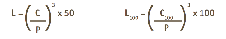
L = Nominal life in km (standard 50)
L100 = Nominal life in km (100)
C = Basic dynamic load rating (at 50km) in Newtons
C100 = Dynamic load rating (at 100km) in Newtons
P = Applied load (Newtons)
Other factors will affect the life as follows.
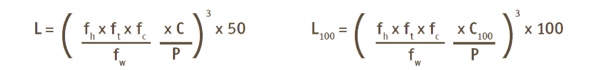
fh = Hardness factor
fw = Load factor
ft = Temperature factor
fc = Contact factor
From the above equations, when the stroke and frequency are constant, the travel life can be calculated by the following equation.
Travel life
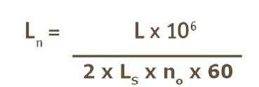
LS = Stroke (km)
no = Number of strokes per minute
Ln = Travel life
L = Nominal life (km)
Calculation example
The maximum applied load and the travel life are the most important factors for choosing the correct size of linear ball bushings. Below are sample calculations for expected travel life and selection of the correctly sized linear ball bushing.
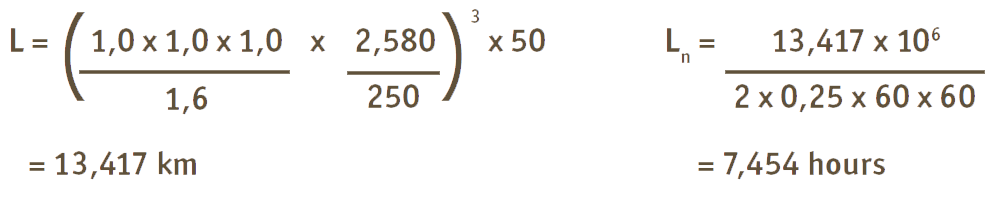
Working conditions
Applied load (P): 250N
Stroke (Ls): 0,25 m
Number of strokes per minute (no): 60
Shaft hardness: HRC 60 (fh = 1,0)
Operating speed (V): 2 x Ls x no = 2 x 0,25 x 60 = 30,000 mm/min (fw = 1,6)
other factors (fc, ft) are considered as 1,0
Calculation of expected travel life
Assuming the basic dynamic load rating is based on travel life of 50km and all other factors are 1,0, you choose the linear bushing size for the life required.
Let’s try Superball bushing L1740.020 with the above working conditions.
Choosing the correct linear ball bushing
Let’s assume our design travel life is 15,000 hours.
L = 15,000 x 2 x 0,250 x 10-6 x 60 x 60
= 27,000 km; and therefore
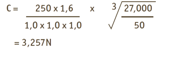
Choosing type L1740 and referring to the table, the correct Superball bushing for the above condition is L1740.025 which has 3,800N as the basic dynamic load rating.
Installation
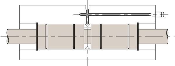
Standard type
Mounted with circlips
Mounted with adapter plates
| For shaft Ø | External (for Shaft) | Internal (for Bore) |
| 5 | P0380.012-A2 | P0381.012-A2 |
| 6 | P0380.012-A2 | P0381.012-A2 |
| 8 | P0380.016-A2 | P0381.016-A2 |
| 10 | P0380.019-A2 | P0381.019-A2 |
| 12 | P0380.022-A2 | P0381.022-A2 |
| 16 | P0380.026-A2 | P0381.026-A2 |
| 20 | P0380.032-A2 | P0381.032-A2 |
| 25 | P0380.040-A2 | P0381.040-A2 |
| 30 | P0380.048-A2 | P0381.047-A2 |
| 40 | P0380.065-A2 | P0381.062-A2 |
| 50 | P0380.075-A2 | P0381.075-A2 |
| 60 | P0380.090-A2 | P0381.090-A2 |
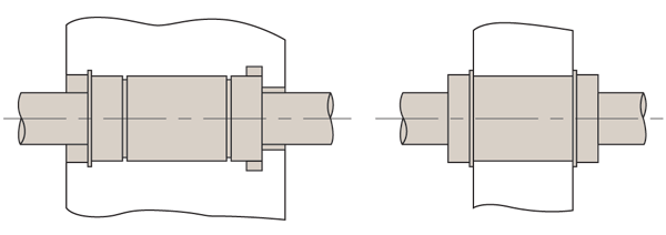
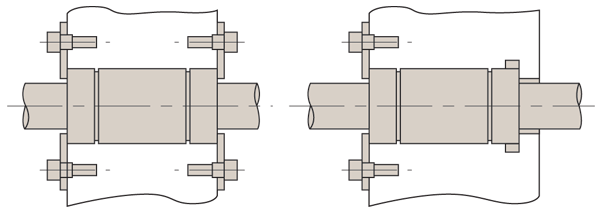
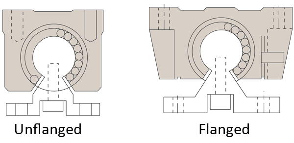
Flange type
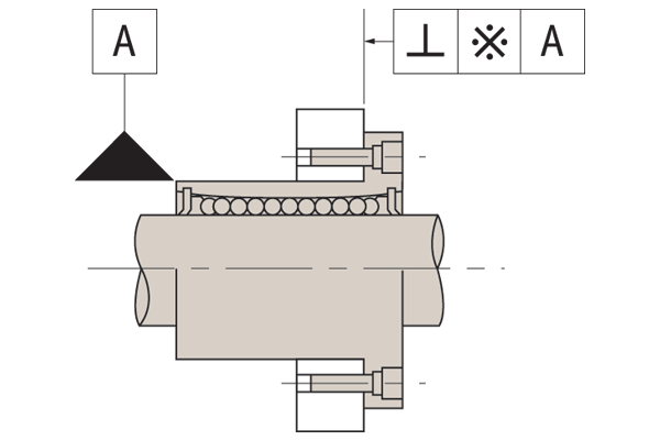
See part tolerances for perpendicularity accuracy when outer sleeve is used as datum for installation.
Adjustable type bearings
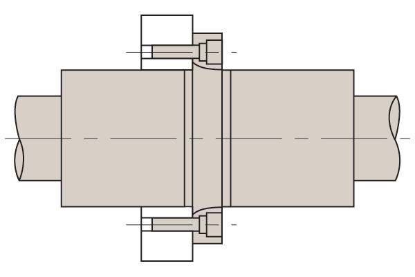
Adjustment of clearance (for adjustable type bearings and shafts), is achieved with an adjustable housing assembly (as shown below). In this case, the slotted side of linear bushing should be located at 90° to the open side of housing for equal radial deformation.
When moment load applies
External loads should be distributed uniformly on a linear bushing. When moment loads are applied, two or more linear bushings should be used on one shaft, and the distance between the two linear bushings should have adequate spacing. Calculate the equivalent load when the moment loads are applied and choose the correct linear bushing.
Mounting of adjustable type bearing
Open type bearings
Open type bearings can be used with a clearance adjustable housing as shown below. Light preload is applied for normal use, heavy preload should be avoided.
Mounting of open type bearing
L1750 Bushing carriages
L1750 carriages can be mounted from both the top or the bottom, minimising assembly time.
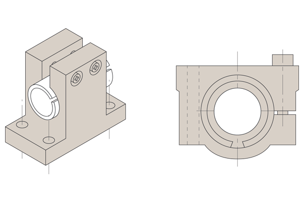
Mounting of case unit
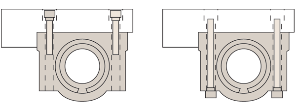
Fixing holes
Carriage fixing holes are threaded from the top a certain distance down. Fixing holes from the bottom are through holes so the screw size when mounting from below needs to be smaller than the thread size if you were mounting from the top.
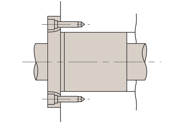
Application tips
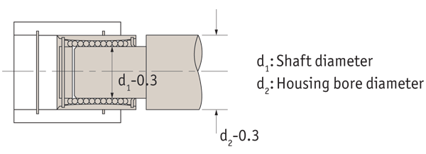
For mounting a standard type linear bushing into a housing, a jig should be used to avoid directly striking the outer sleeve or seal during installation.
Mounting into housing
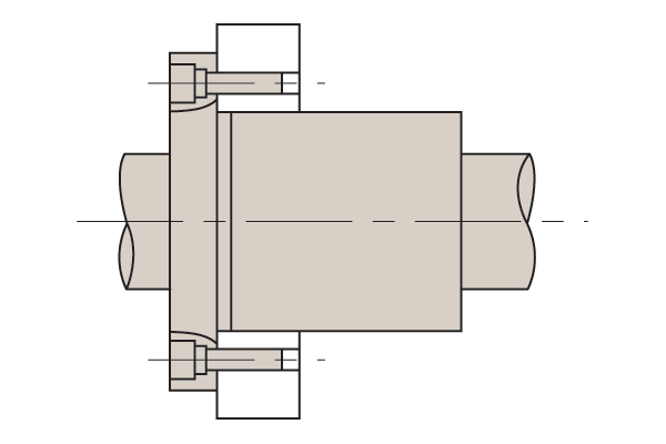
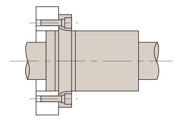
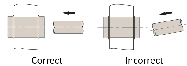
Insertion of shaft
Care must be taken when inserting a shaft into a linear bushing. If the shaft is inserted incorrectly, the ball retaining cage may be damaged and the balls loosened from position.
Insertion of shaft into linear bushing
Rotational motion prohibited
Linear bushing are not suitable for rotational motion. If the linear bushing is exposed to rotational motion it may lead to unexpected accidents.