
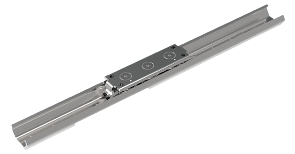
Automotion Components X-Rails
What is...
Features
The X rail system is a highly cost-effective product made of zinc plated steel (L1970), the stainless steel version (L1971) has a high level of corrosion resistance.
Cost-effective and corrosion resistant
The X rail is relatively inexpensive as it is based on a rolled formed, steel section. It allows for adjustments due to misalignment of the structure that it is being used on and with internal raceways is suited for robust use but is not suitable for applications having signifi cant moment loads.
The stainless steel (316L) version uses FDA and USDA compliant materials.
Stocked
Same day despatch for lengths of up to 3 metres.
Zinc-plated version
3 sizes to allow the most cost-effective solution for light and heavy duty applications.
Stainless steel version
- High grade stainless (316L).
- For wet applications.
- 2RS (splash-proof) seals.
Flexibility in set-up
X rail allows the sliders one rail to remain fixed in place but allows some lateral movement of the sliders in the other rail to adapt to any misalignment.
T and U rail allows for misalignment
Using two T rails good set-up accuracy is required
Specifications and applications
Specifications
- Maximum speed 1,5 m/s.
- Maximum acceleration 2 m/s2.
- Maximum rail length 3120 mm.
- Three rail sizes 20, 30 and 45.
- Temperature range steel -30°C to +120°C.
- Temperature range stainless -30°C to +100°C.
- Sliders have two fixed rollers and one eccentric roller for adjustment of preload.
- Two slider body types; solid slider version and low profile slider version (T rails only).
- Joining of rails together, if required please discuss with our Technical Department.
- Not suitable for large moment loads (in this case use two or more sliders/rails to reduce moment loads).
- For applications with high moment and/or higher precision loads please use our Compact Rail System.
Applications
Safety guarding
Extending protective systems
sliding gates
automatic pick & place
Sliding doors & windows
Internal sliding doors
gates • roof lights
display cases
Medical technology
X-ray equipment
dental chairs
bed extensions
Food, drink & pharmaceuticals
Food handling conveyors
pharmaceutical factories
stainless display equipment
Transport (naval)
Sliding hatches
pull-out storage
Transport (rail)
Seat adjustment
sliding doors
battery removal units
Transport (automotive)
Ambulance sliding systems
fire fighting vehicles
sliding panels
Transport (military)
Sliding seats
protective hatches
stretcher extensions
Water & waste
Sliding protective hatches
wash down applications
water tank doors
Product Selection
Rail types
L1970 Zinc-plated steel version
Solid body slider
L1970.CEST/U
(2Z dust proof seals)
Low profile slider
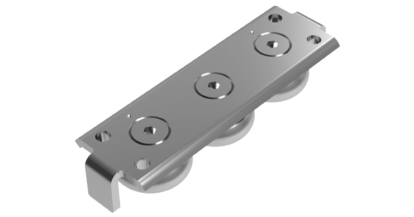
L1970.CES
(2Z dust proof seals)
T Rail (master)

L1970.TES
U Rail (slave)

L1970.UES
L1971 Stainless Steel version
Solid body
L1971.CEXT/U
(2RS splash proof seals)
Low profile slider
L1971.CEX
(2RS splash proof seals)
T Rail (master)
U Rail (slave)
General Guidance
Rail selection
T Rail (master)
Accepts radial and axial loads
U Rail (slave)
Radial loads only
Compensates for misalignment
Selecting the correct rail
Firstly
The decision needs to be made if zinc plated steel or stainless steel rails and sliders are required.
- The zinc plated steel version (L1970) of the product is considerably less expensive than the 316L stainless steel type (L1971).
- The rollers in the zinc plated (L1970) sliders are protected by 2Z metal bearing covers. These are not meant to be used in anything other than a dry environment.
- The L1971 stainless steel X rail system is resistant to water and many chemicals. The slider rollers have rubber 2RS roller seals – being water resistant (not to be used fully submersed).
Secondly
The size of system to be used is selected.
- There are three diff erent rail and slider sizes: 20, 30 and 45.
- The load that is being carried and its shape needs to be considered. The X rail system is not really suited for moment loads. If moment loads exist then two or more rails/sliders should be used to off set this. Typically 2, 4 or more sliders are used and the load carried should be divided over the number of sliders bearing in mind that if using a U rail slider along with a T rail, the U rail sliders do not have any axial load capacity.
- The rails are supplied in standard lengths of 1040mm, 2080mm and 3120mm – and can easily be cut to other required lengths by Automotion (on request).
Finally
Decide whether a low profile slider or a solid body slider is required (low profile sliders are only available for T rails). The low profi le (L1970.CES and L1971.CEX) sliders are less expensive than the solid body sliders.
Please note
It is very important to ensure that the correct low profile fixing screws are used with this rail (see part no. L1970.S for zinc plated steel and L1971.S for stainless steel). Using other higher profi le heads may lead to contact between the underside of the slider and the top of the screws.
Technical Specs
Set-up
T rails (master) and U rails (slave)
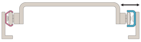
It is often the case, with the X rail system, that two T rails are used in the system design. However, where there are substantial alignment issues it is better to use a T rail (master) and U rail (slave) as below.
This allows the slider in the T rail to remain fixed in the place, but allows some lateral movement of the sliders in the U rail to adapt to any misalignment and avoid any issues of stiction.
U rails have flat parallel raceways that allow free lateral movement of the sliders. The maximum lateral movement for each size rail is shown in the table that follows.
T and U rails
T and U Rail: Allows for misalignment
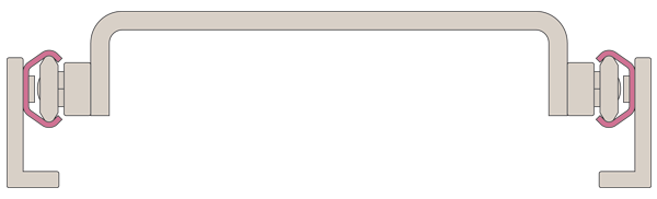
T and T rails
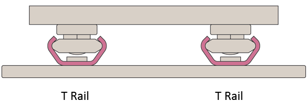
Some customers prefer to use two T rails as shown below. Whilst this is acceptable, a greater degree of accuracy is required in the structure on which the system is used.
Two T rails: Good set-up accuracy required
It is however also acceptable (but not the preferred method), to use the rails as below but the alignment accuracy needed is slightly greater and in this set up only T type rails can be used. In this instance we recommend the use of solid body sliders L1970.CEST (steel) or L1971.CEXT (stainless) rather than the low profile sliders.
Ensure a significant margin of safety is applied to the load ratings or consider using our hardened steel Compact Rail System.
Load capcity
L1970 and L1971 slider load ratings for T rails
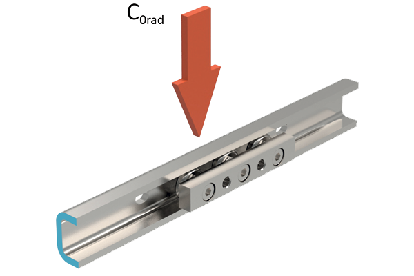
| Part no. | Material | Body | C0rad N | C0ax N |
| L1970.20T-060 | Steel | Solid | 326 | 185 |
| L1970.30T-080 | Steel | Solid | 870 | 435 |
| L1970.45T-120 | Steel | Solid | 1740 | 935 |
| L1970.20T-080 | Steel | Low Profile | 326 | 185 |
| L1970.30T-088 | Steel | Low Profile | 870 | 435 |
| L1970.45T-150 | Steel | Low Profile | 1740 | 935 |
| L1971.20T-060 | Stainless Steel | Solid | 300 | 170 |
| L1971.30T-080 | Stainless Steel | Solid | 800 | 400 |
| L1971.45T-120 | Stainless Steel | Solid | 1600 | 860 |
| L1971.20T-080 | Stainless Steel | Low Profile | 300 | 170 |
| L1971.30T-088 | Stainless Steel | Low Profile | 800 | 400 |
| L1971.45T-160 | Stainless Steel | Low Profile | 1600 | 860 |
L1970 and L1971 slider load ratings for U rails
| Part no. | Material | Body | C0rad N | C0ax N |
| L1970.20U-060 | Steel | Solid | 326 | - |
| L1970.30U-080 | Steel | Solid | 870 | - |
| 1970.45U-120 | Steel | Solid | 1740 | - |
| L1971.20U-060 | Stainless Steel | Solid | 300 | - |
| L1971.30U-080 | Stainless Steel | Solid | 800 | - |
| L1971.45U-120 | Stainless Steel | Solid | 1600 | - |
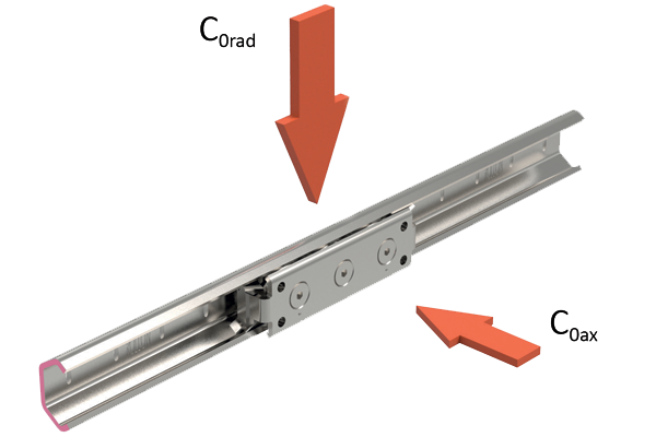
Orientation of rails
The radial load that the sliders can take is significantly higher than the axial load, so where possible the rails should be set up with the sliders taking the loads in this plane.
Recommended
Non-preferred
Radial load rating is typically 2 x axial load rating
FAQs
Why should I consider using the X Rail system?
The X rail system is very cost-effective.
Using a master (T rail) and slave rail (U rail), the structure onto which the rail is installed does not have to be machined as accurately as when using other rail systems - this can result in major cost savings for many projects.
It is highly resistant to dirt. The L1971 stainless steel X rail is very corrosion resistant and can be used in wet environments (not submerged).
Are there any disadvantages?
The X rail system is made of a rolled formed section. It is not suited to high moment loads. If moment loads are present then typically more sliders and/or an extra rail is used to provide a system where less moment loads are applied to the sliders.
If you have applications with significant moment loads we would recommend the use of our Compact Rail System which is made from cold drawn steel section and has hardened raceways.
How do I change the smoothness of the running of the sliders in the rails?
Each slider is supplied with a small spanner. This can be used to push the eccentric roller towards the top of the rail (making it run more stiffly), or pulled away slightly to make the sliders run very smoothly. The eccentric rollers are clearly marked and the slider should be installed the correct way up in the rail. Generally this is with the fixed rollers towards the bottom of the rail (providing the loading points). The simple instructions are shown in the catalogue.
I want to use the rail outside or in a slightly wet environment?
The stainless steel version (L1971) is made of highly corrosion resistant 316L stainless steel. The rollers are also stainless steel but harder (440C stainless) and are fitted with 2RS rubber seals (splash proof). They can be used outside and in marine applications (e.g. sliding doors and hatches).
Do you hold these parts in stock?
Yes
Can I get CAD files of these parts?
Most of the 3D models (in many formats) are available for download directly from our website www.automotioncomponents.co.uk
Set-up
Slave rail compensation
In a T+U-System, the slider in the T rail carries axial and radial loads and guides the movement of the slider in the U rail. U rails have fl at parallel raceways that allow free lateral movement for the sliders.
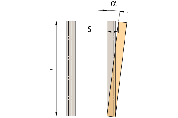
The maximum freedom a slider in the U rail can offer can be calculated using the values S1 and S2. With nominal value Bnom as the starting point, S1 indicates the maximum allowed movement into the rail, while S2 represents the maximum off set towards the outside of the rail.
If the length of the rail is known, the maximum allowable angle of deviation of the mounting surface is shown below. In this case the slide in the U rail has the freedom to travel from the innermost position S1 to the outermost position S2.
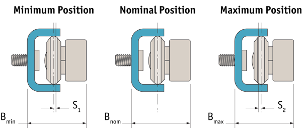
| U rail size | S1 | S2 | Bmin | Bnom | Bmax |
| 20 | 0,60 | 0,60 | 17,65 | 18,25 | 18,85 |
| 30 | 1,00 | 1,00 | 26,95 | 27,95 | 28,95 |
| 45 | 1,75 | 1,75 | 35,50 | 37,25 | 39,00 |
Guideline for maximum angle deviation α, achievable with the longest guide rail
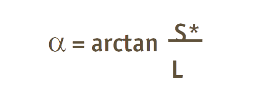
S* = sum of S1 and S2
L = length of the rail
| Size | Rail length | Off set S* | Angle α ° |
| 20 | 3120 | 1,2 | 0,022 |
| 30 | 3120 | 2,0 | 0,037 |
| 45 | 3120 | 3,5 | 0,064 |
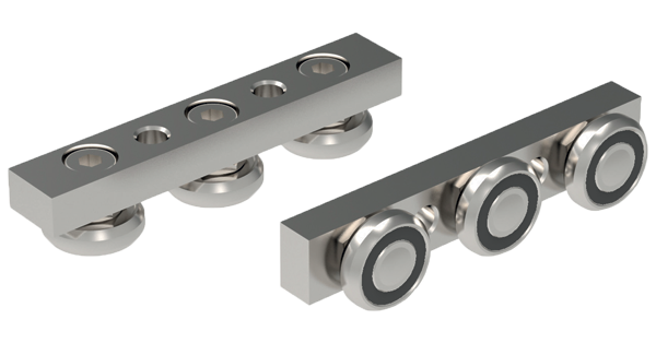
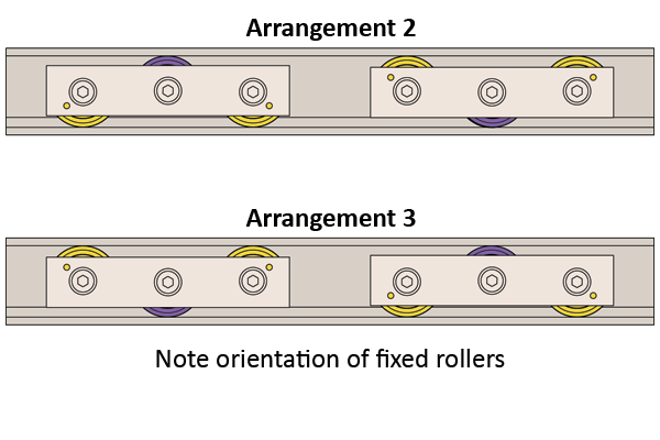
Slider arrangements
The standard arrangement of the sliders (when used in a horizontal application) is as follows:
Arrangement 1

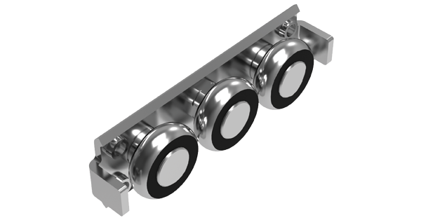
For other applications (e.g. horizontal or vertical) the alternative arrangements are as follows:

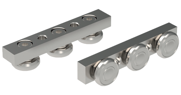
Adjusting the sliders
If delivered separately, or if the sliders need to be installed in another rail, the sliders must be re-adjusted. In this case, follow the instructions below.
The “•” or “V” marked on the slider indicates the direction of the fi xed rollers.
The sliders have three large rollers. The two at either end are fixed and the direction of these fixed positions is marked on the sliders with a dot or an arrow.
Insert the sliders into the rails with the fixed rollers set to take the load in the best direction.
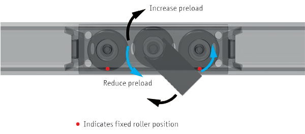
The middle roller is on an eccentric pivot that is easily adjusted (using the thin spanner that is supplied with them and a hexagon key). This allows the preload of the system to be set as required – stiff or free running.
Generally the sliders will not be inserted into the rails when leaving the factory. To set the sliders to the required preload is a simple procedure:
- Ensure raceways are clean.
- Remove the small plastic wipers (from the low profile sliders) and insert the slider into the rail.
- Slightly loosen the centre roller (using the spanner and a hexagon key).
- For U rails a packer should be used to set the slider in its middle lateral position.
- Use the flat spanner provided to move the middle roller on its eccentric to adjust the stiff ness of its running. Not too loose so that there is excess play and not too tight that a lot of friction is generated.
- Lock the roller in the desired position with the spanner and a hexagon key.
- Move the slider the length of the rail to check required running – it should move easily with no play at any point on the rail.
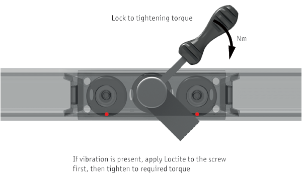
- Tighten the fixing screw to the correct torque – whilst holding the spanner in place to ensure no further movement (see correct torque values in table below.
- Finally (if using a slider with a wiper), re-install the wipers if required.
| Size | Tightening torque Nm |
| 20 | 3 |
| 30 | 7 |
| 45 | 12 |